Homebuilt CNC – Part 1
Not much content around here in a while but this will be a small series on the journey I took learning about CNC and constructing my own CNC machine out of mainly stuff I had lying around or was able to scavenge.
Way back in year 11 I brought home two tops off the top of school desks, thinking the plywood with a hard resin(?) surface would make a great base for a CNC machine. Some decent size stepper motors were scavenged from a few old dot matrix printers to drive the axes (printers by the way are home to all manner of handy little electro-mechanical bits that come in handy with projects) and Polulu A4983 Stepper drivers were purchased to drive the stepper motors.
A basic XY table was set up using just the tabletops, and stepper motors were set up with some 3/16" threaded rod to shit the axes. A few little Arduino test scripts were created, to shift it backwards and forwards and then all progress stopped as I wasn't quite sure how to go about doing the software side of things to turn plans into commands, the project got shelved and sat gathering dust behind the lounge for the better part of 3 years.
So after a year of uni and a cadet ship the machine was rediscovered during a clean up and over the next few months slowly evolved into what is probably one of the coolest things I have ever built.
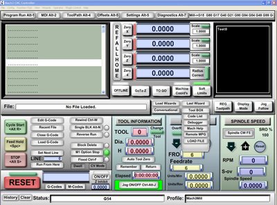
Googling around revealed that pretty much all hobby cnc mills or 3d printers are run over a parallel port which is able to be more or less used as time accurate IO leaving you with a relatively beefy processor to run "g-code". G-code at its most simple is a series of instructions on how the machine should move around and how it should move there. You then need some software to parse this and give the machine itself the commands. For testing I downloaded the trial version of Mach3 allowing me to run 500 lines of G-code. Mach3 is a program that parses G-code and sends out pulses on the different pins of the parallel port, that you hook up to the "step" and "direction" lines on stepper drivers allowing for very little in the way of required electrics or programming on my part.
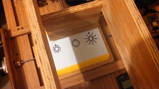
This leaves you with another problem, how to generate the g-code for Mach3 to run as it really wouldn't be much fun to write anything but the most basic jobs by hand. There are all sorts of methods you can use to turn designs into g-code but for my very first tests I used this neat script to generate some patterns. With some more plywood framework screwed down to the base as the beginnings of a z axis a pen was taped on, and here are the results.
It was slightly wobbly, had a big blotch from where the pen stopped, but it mostly worked and it felt awesome.
Next part coming soon (Hopefully).
Breadboard design
I know I haven't put anything up in ages and there are a whole bunch of things I have been working on that hopefully make it here.
This is just a short post to display a really terrible piece of design work.
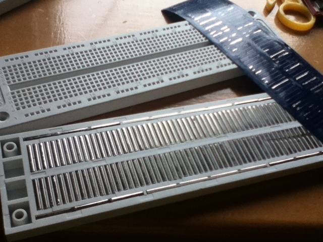
After much frustration with some cheapo breadboards off eBay I finally pulled off the protective layer on the back of the breadboard to see if there was some kind of funny design going on.
Turns out somebody thought it would be a great idea to split the power rails down each side of the breadboard into 3 segments without marking it on the top of the board.
Well that's one headache solved now back to finding the bugs in the circuit design


