Homebuilt CNC – Part 2
It seems the pattern here is the first paragraph comments on how long it has been since I have written things up, my post drafts folder is filled with skeletons of posts that have never really gotten finished off, hopefully this post gets finished.
Since the last post I have finished construction of my basic CNC machine, the Z axis is complete and I make use of a dremel for the cutting head, as there are a wide variety of bits availible on ebay that will suit its 3.175mm collet.
The electronics has remained virtually the same but I have upped the power supply voltage to 24V to get a bit faster stepping speed, and broken out some more pins from the parallel port to allow "touching off" when milling PCB's.
Through poor planning I cant find any photos of the finished rig, if I come across any I will insert them here.
What I can talk about are the tools I have been using for the generation and execution of G-Code, with a few project photos thrown in.
Running the G-Code
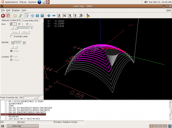
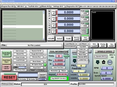
Since the end of the last post I have swapped from using Mach3 to LinuxCNC partially because I was only running a trial version of Mach3 and Linux CNC is free, partially because I was getting sick of looking at the interface in Mach3.
Setup was pretty straightfoward, download the live CD, try it out, hit install. Linux CNC even comes with a neat helper tool to allow easy setup and tuning of stepper motor based machine.
The software has been pretty easy to use, and provides a good set of basic functionality, it is however missing all of the little "wizards" that Mach3 had for generation of short jobs like "cut a pocket this size in this location" or "drill this pattern of holes".
Generating G-Code
I have been using two tools to generate G-Code. F-Engrave a free python program for generating V-Carving toolpaths, and the trial version of cambam, software for the setup of more complex jobs, as well as limited cad functionality.
F-Engrave
One problem with milling something with a rotating cutter is that you will always end up with rounded corners in the holes of pockets and cutouts as you are cutting with a circular bit. There are many different solutions that people use to try and counter this. The most common approaches are. Use a CNC machine with more axes, so it is able to cut from a different angle to remove the remaining material, however this is expensive, and beyond what can be knocked up with plywood at home. Over-cut corners, if you need to be able to fit a square bit object into a milled pocket, you can overcut and take out extra materials at the corners to leave a pocket a square object will fit into.

Some of the different ways you can over cut a corner, this is sometimes called dog-boning because of the shape it causes.
Another option is to reduce the radius of the cutter, the smaller the cutter you use the less rounded and more sharp the inside of a pocket is, the trade-off being the strength of the cutter and how many passes you need to remove the material from the inside of the shape. Which brings us to the last option which is to use a V shaped cutter and some fancy software to be able to use a virtual 0 diameter cutter to get very sharp corners. How it works is by using a V shaped cutter and ramping it towards the surface as you near a corner, producing a finer and finer corner as you reach the surface of the material, while this is not suitable for everything, i.e. fitting a square block into a hole, it works great for tasks like signs.
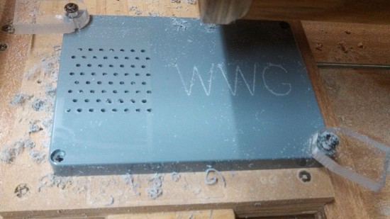
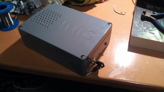
I used F-engrave to produce a number of items like this including some labels and vinyl stamps.
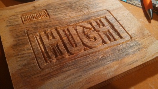
First ever runs of the machine with the dremel, had not got all the settings and tuning quite worked out.

Some vinyl stamps, vinyl was epoxied down to some pine, F-engrave was used to mill the stamp and Cambam to do the cutout work, you can see the play in the mechanical setup of the machine where multiple passes were made to get through the wood.
Cambam
Cambam is a software package that allows the creation of tool paths from DXF files, it also has and inbuilt editor for editing geometry or creating simple designs. Its a pretty handy program and I think I will end up buying the full version when I run out of trial time.
Due to a combination of camera and computer issues this is more or less the only pictures/video I have of the more or less finished machine
Visolate
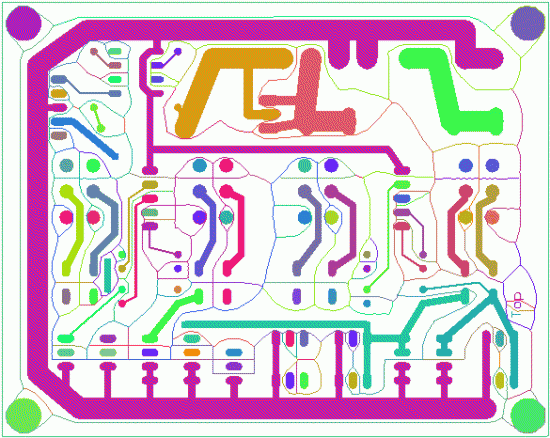
A handy little tool for reducing the amount of milling needed to create PCBs instead of milling precisely around each trace it mills one line between each signal, much faster to mill but produces some off looking tracks.
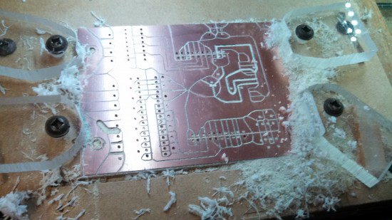
For the first go ever milling a board I had a few depth issues as well as plowing though my hold-down brackets, at least they are only acrylic. After this step the board gets milled to its final shape. I even had reasonable success with milling a double sided board.
And that's about it for this project, due to moving houses the setup has been packed away into storage and wont be seen again for months. Overall it was a pretty neat little setup that cost next to nothing, the only money that really went into the project was for the stepper driver boards and a range of end mills, all of which can be procured fairly cheaply from ebay. Everything else was scavenged and jumbled together until this was the result.
Only a slight gap between now and the last post.
Homebuilt CNC – Part 1
Not much content around here in a while but this will be a small series on the journey I took learning about CNC and constructing my own CNC machine out of mainly stuff I had lying around or was able to scavenge.
Way back in year 11 I brought home two tops off the top of school desks, thinking the plywood with a hard resin(?) surface would make a great base for a CNC machine. Some decent size stepper motors were scavenged from a few old dot matrix printers to drive the axes (printers by the way are home to all manner of handy little electro-mechanical bits that come in handy with projects) and Polulu A4983 Stepper drivers were purchased to drive the stepper motors.
A basic XY table was set up using just the tabletops, and stepper motors were set up with some 3/16" threaded rod to shit the axes. A few little Arduino test scripts were created, to shift it backwards and forwards and then all progress stopped as I wasn't quite sure how to go about doing the software side of things to turn plans into commands, the project got shelved and sat gathering dust behind the lounge for the better part of 3 years.
So after a year of uni and a cadet ship the machine was rediscovered during a clean up and over the next few months slowly evolved into what is probably one of the coolest things I have ever built.
Googling around revealed that pretty much all hobby cnc mills or 3d printers are run over a parallel port which is able to be more or less used as time accurate IO leaving you with a relatively beefy processor to run "g-code". G-code at its most simple is a series of instructions on how the machine should move around and how it should move there. You then need some software to parse this and give the machine itself the commands. For testing I downloaded the trial version of Mach3 allowing me to run 500 lines of G-code. Mach3 is a program that parses G-code and sends out pulses on the different pins of the parallel port, that you hook up to the "step" and "direction" lines on stepper drivers allowing for very little in the way of required electrics or programming on my part.
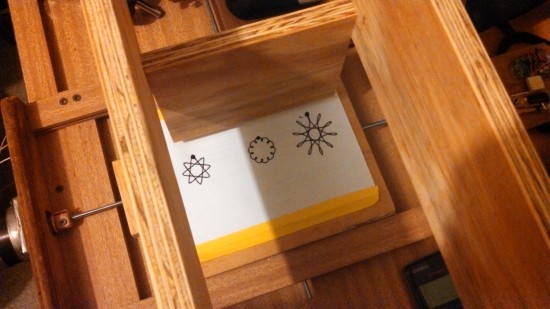
This leaves you with another problem, how to generate the g-code for Mach3 to run as it really wouldn't be much fun to write anything but the most basic jobs by hand. There are all sorts of methods you can use to turn designs into g-code but for my very first tests I used this neat script to generate some patterns. With some more plywood framework screwed down to the base as the beginnings of a z axis a pen was taped on, and here are the results.
It was slightly wobbly, had a big blotch from where the pen stopped, but it mostly worked and it felt awesome.
Next part coming soon (Hopefully).
